Small scale mass-production with Lotta

This is just a short collection of photos, I’ll write more about lessons learned as replies.

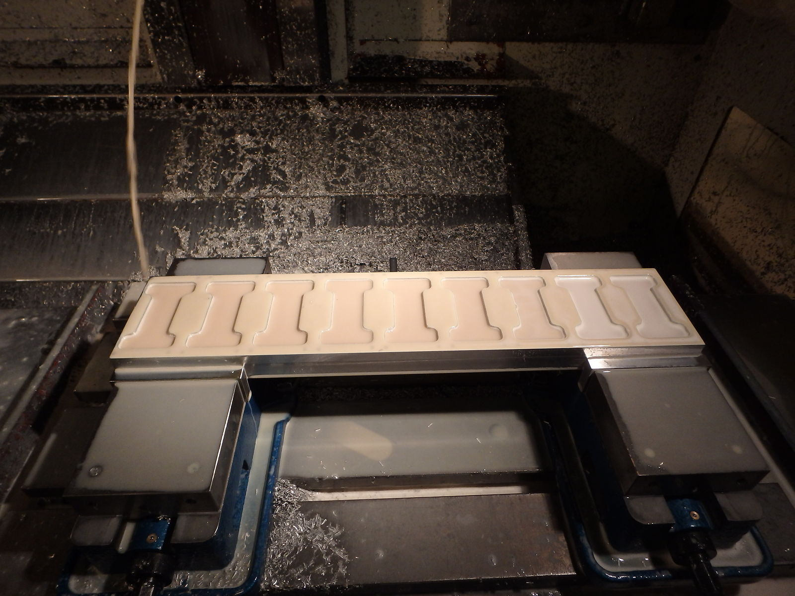
Step one: Make a prototype to test that your CAM results in what you want

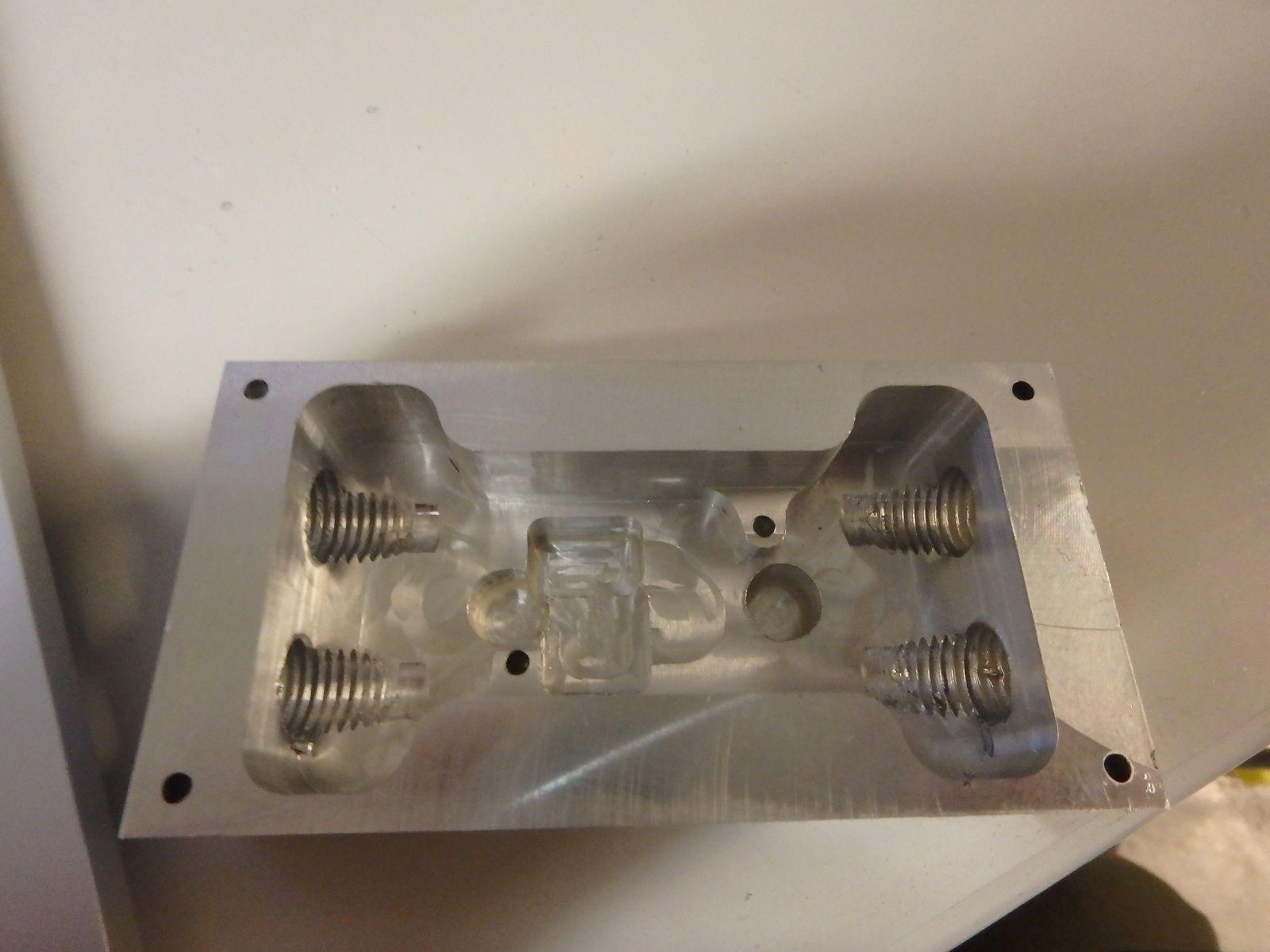
(step 1.5 experiment to find fastest feed parameters that do not ruin your tools and result in acceptable finish)

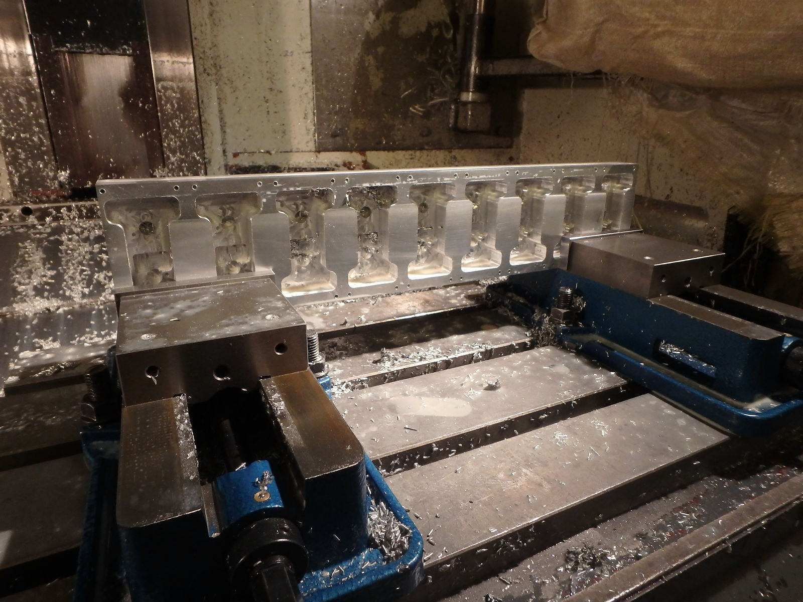
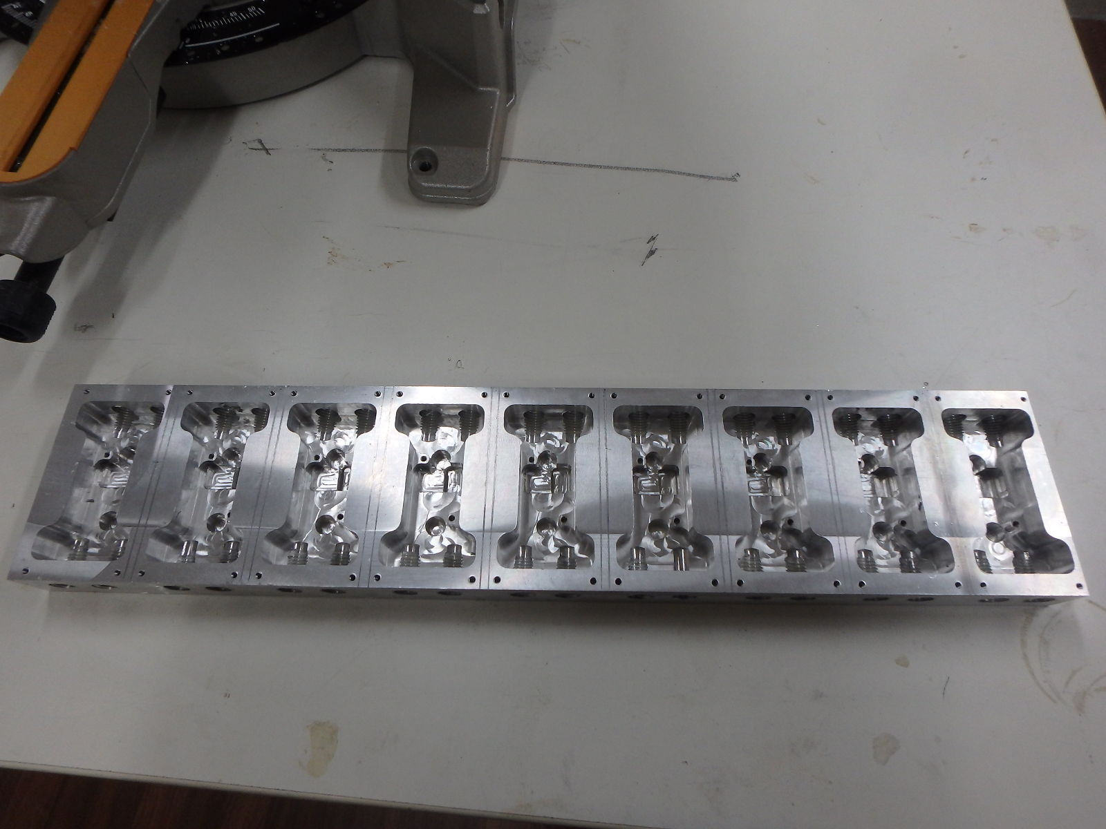
Step two: find out the number of pieces you can find on the working area, the X is 500mm and the result (after taking into account 3mm allowance for sawing the pieces separate) was 9 (474mm wide billet)

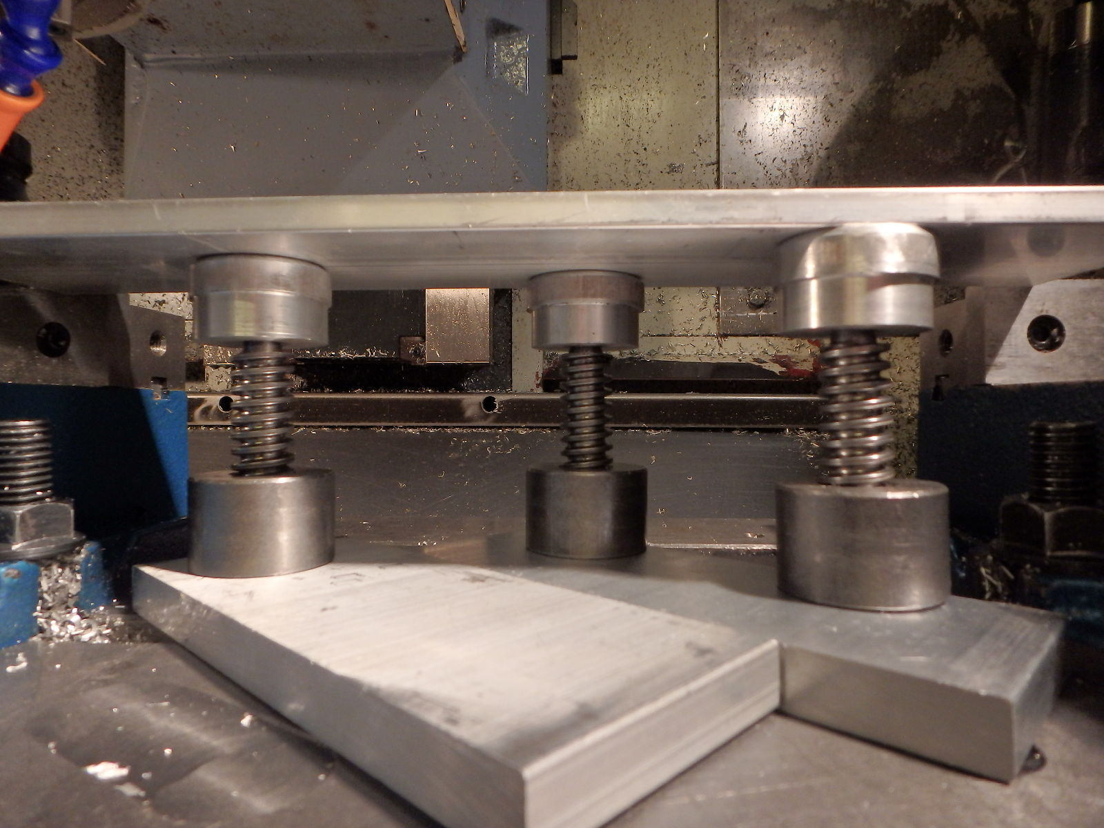
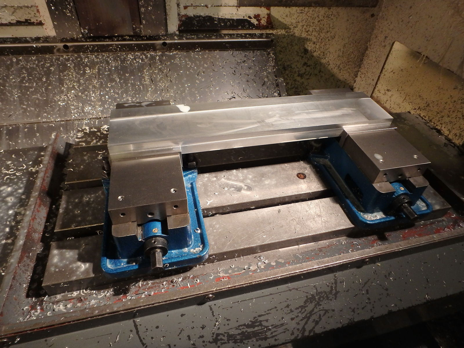
Step three: make sure you have two vices aligned within your tolerances (better than 0.01mm).

Step four: get a big honking piece of billet and face it square

Step five: generate the GCode with subprograms for all operations, preferably ordered by tool. Tool changes take surprisingly long.

Step six: edit the main program, copy the subprogram calls and add WCS changes betweeen them, also edit the subprograms and take out the WCS changes, also if tool changes are in the subprogram (like Fusion360 likes to do) move them to the main program. This requires understanding GCode and being able to write it by hand, but we require that from any Lotta operator anyway…

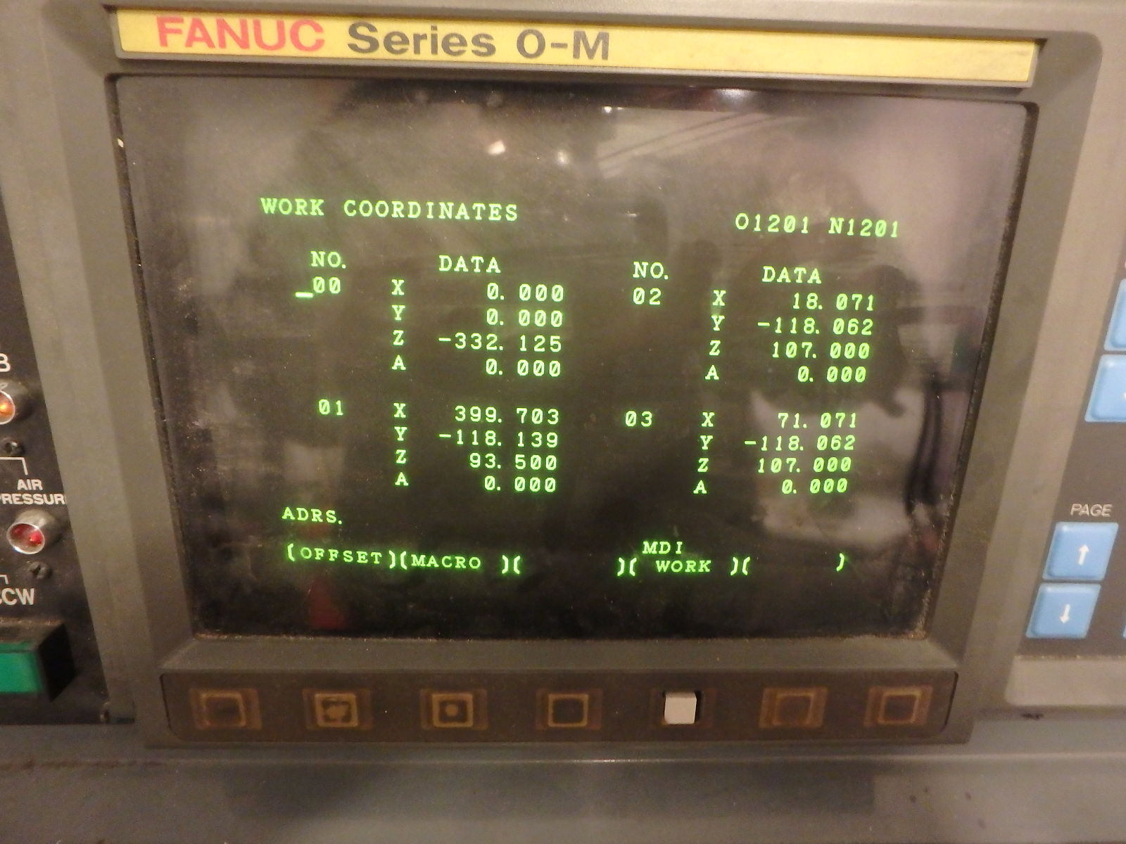
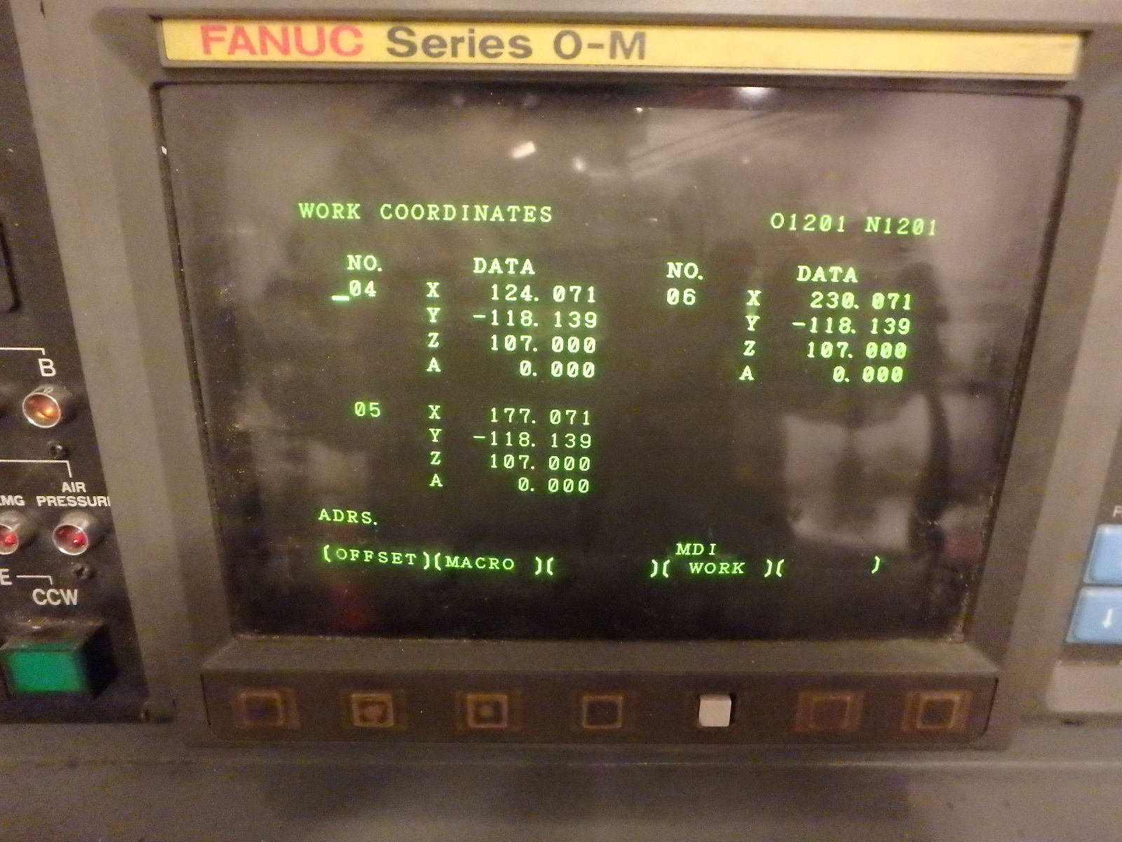
Step seven: measure, calculate and enter the WCS offsets, Lotta has 6 of them and since I had to do two runs in any case I chose 5 and 4 as the number of pieces to mill in one go (and made two separate copies of the main program for this)

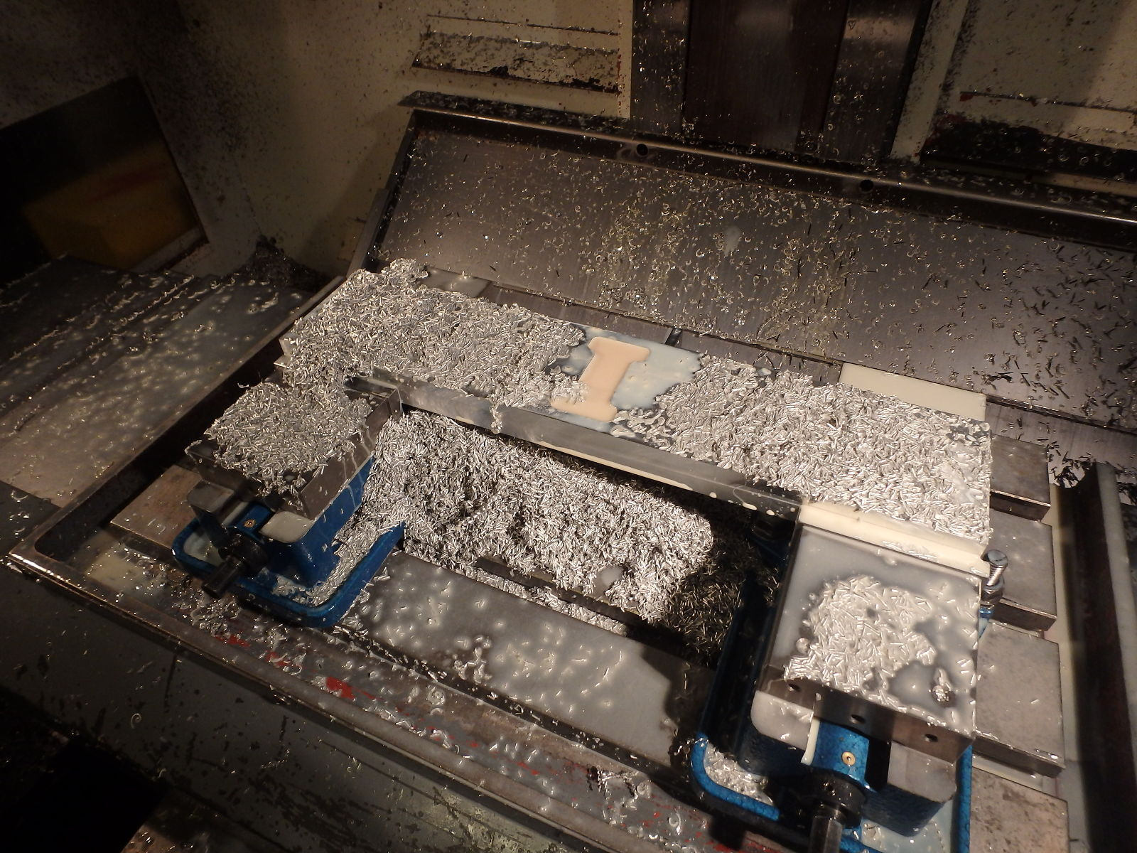
Step eight: run your program, remember to clean the chips away between tool changes:

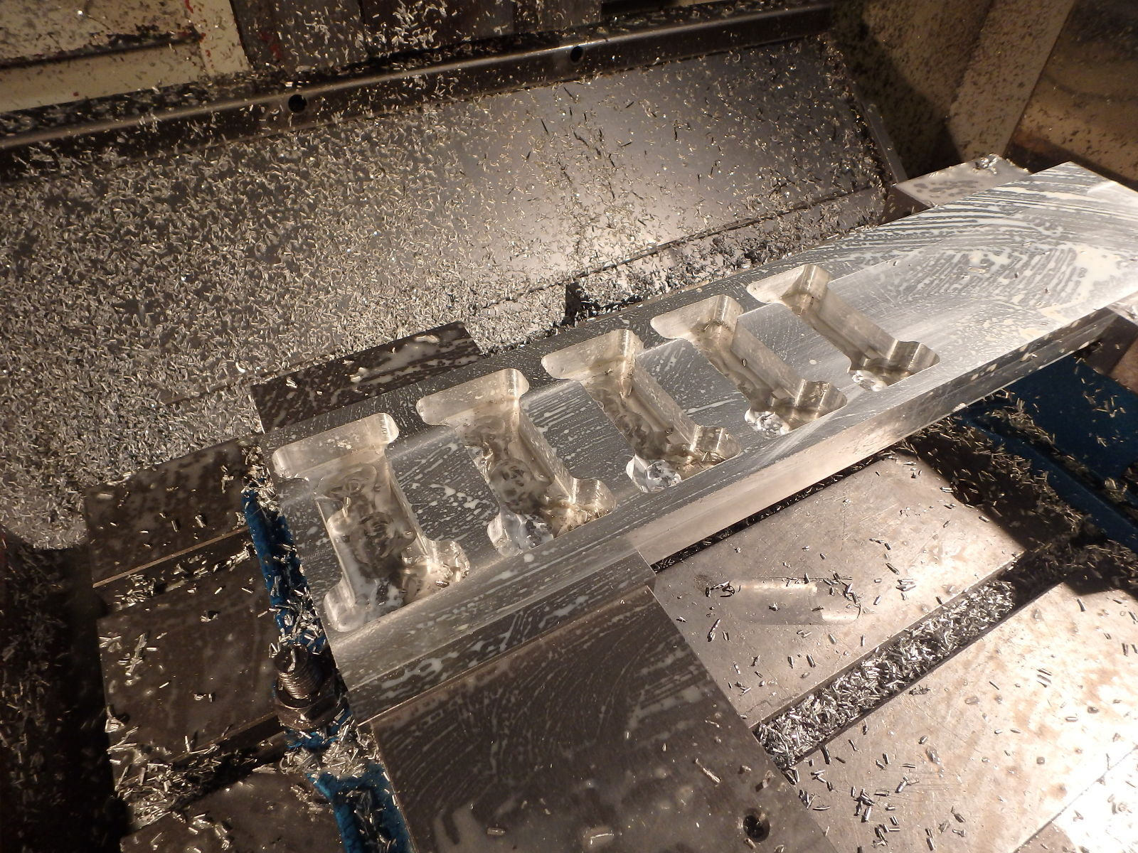
Step nine: keep updating the offsets and re-running your program until this setup is done

Step ten: Next setup, as previous setup, repeat for all setups…

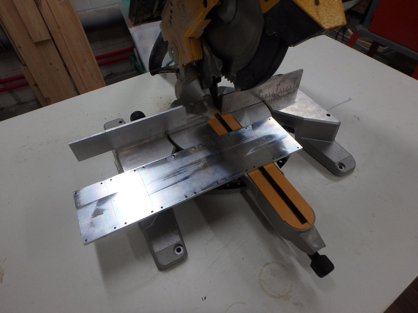
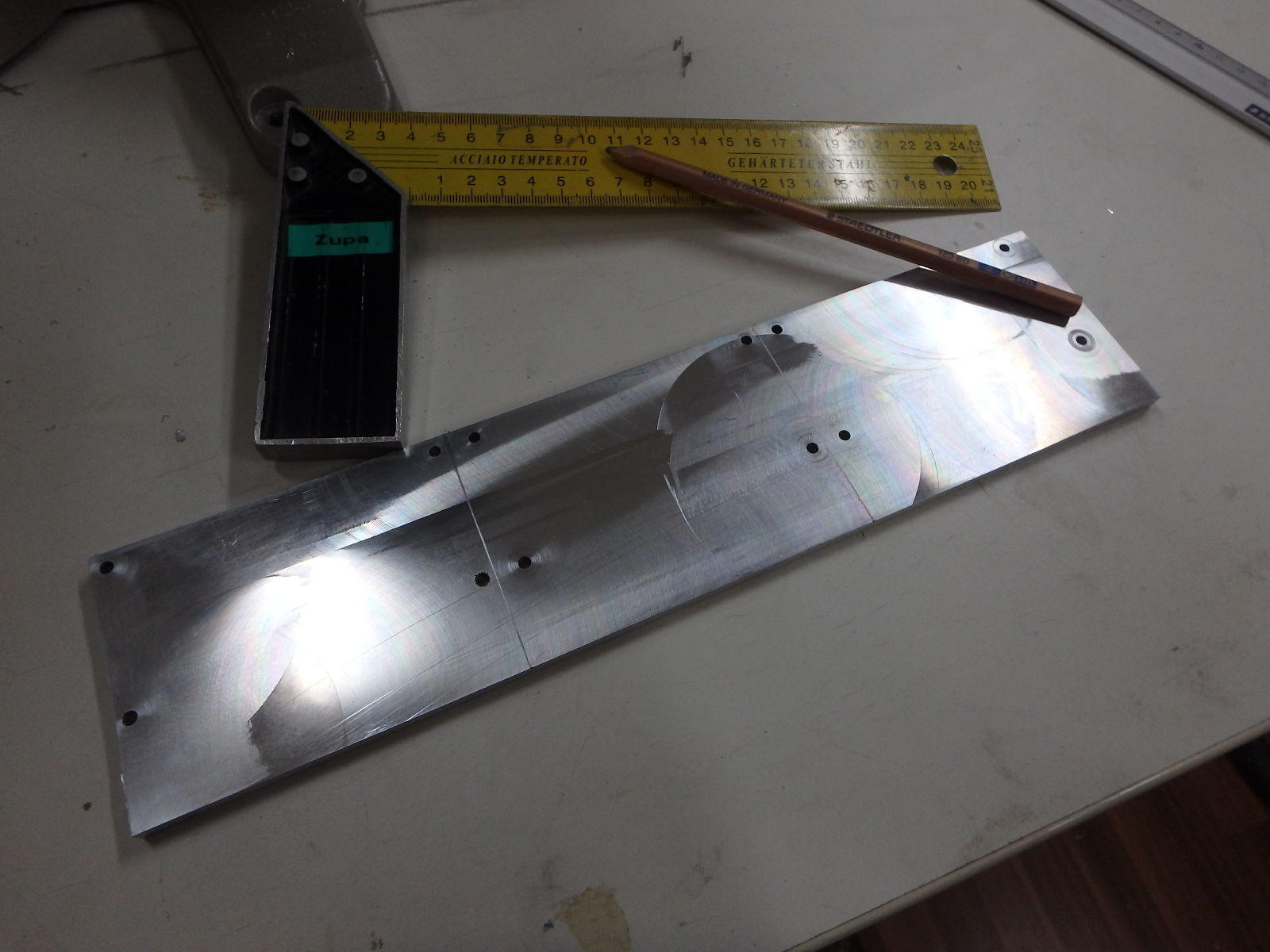
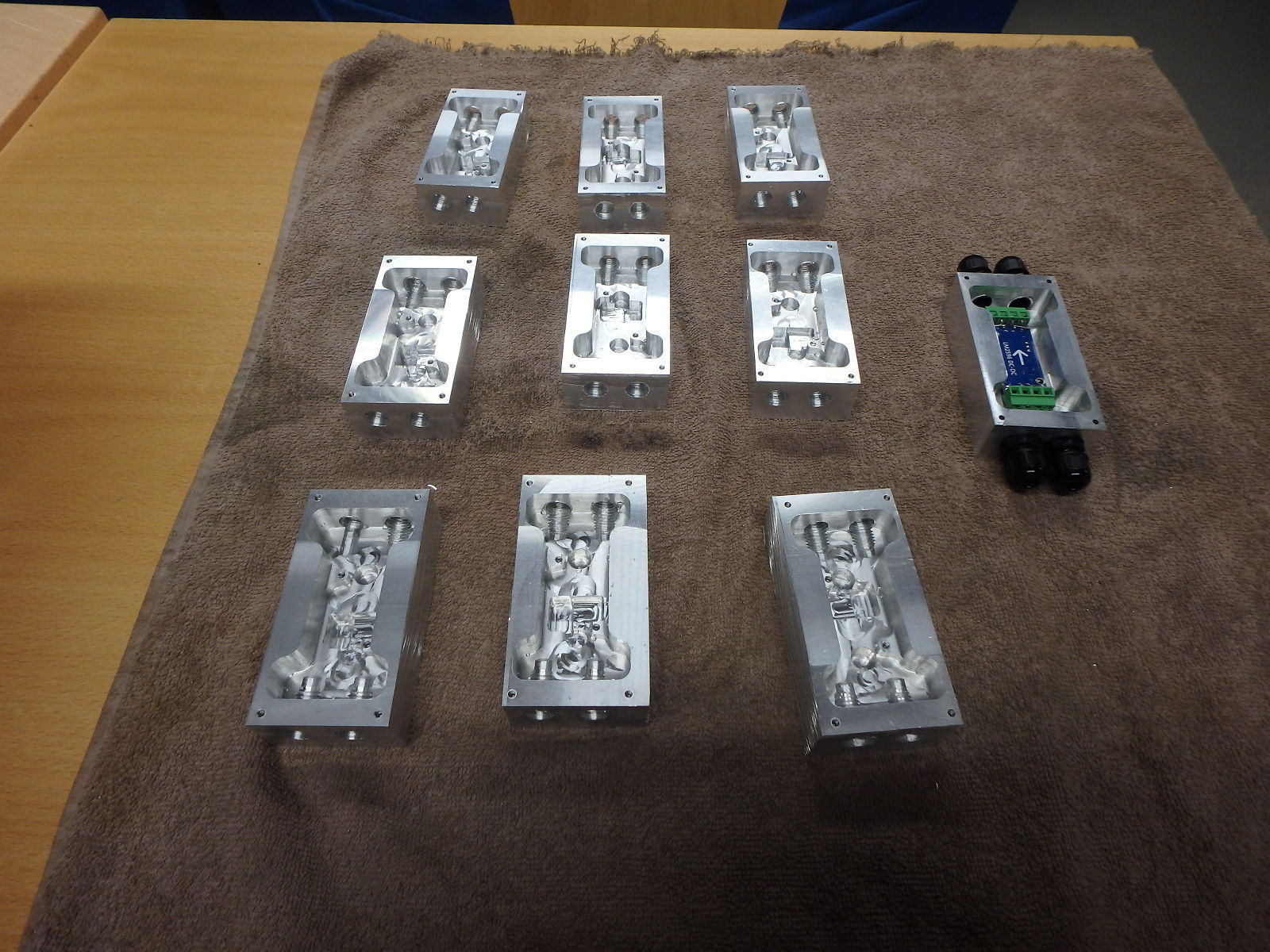
Step eleven: measure and mark where to cut the pieces apart, make if the blade cut wider than your marking line, draw two lines and make sure the blade aligns between them, in this case lines are 3mm apart since the circular saw has blade 3mm wide…

Step twelve: clean (with lot’s of running water for example) away all chips remaining in cavities, dry the pieces thoroughly (use hot-air blower if needed), try to wash away that cutting fluid residue too.

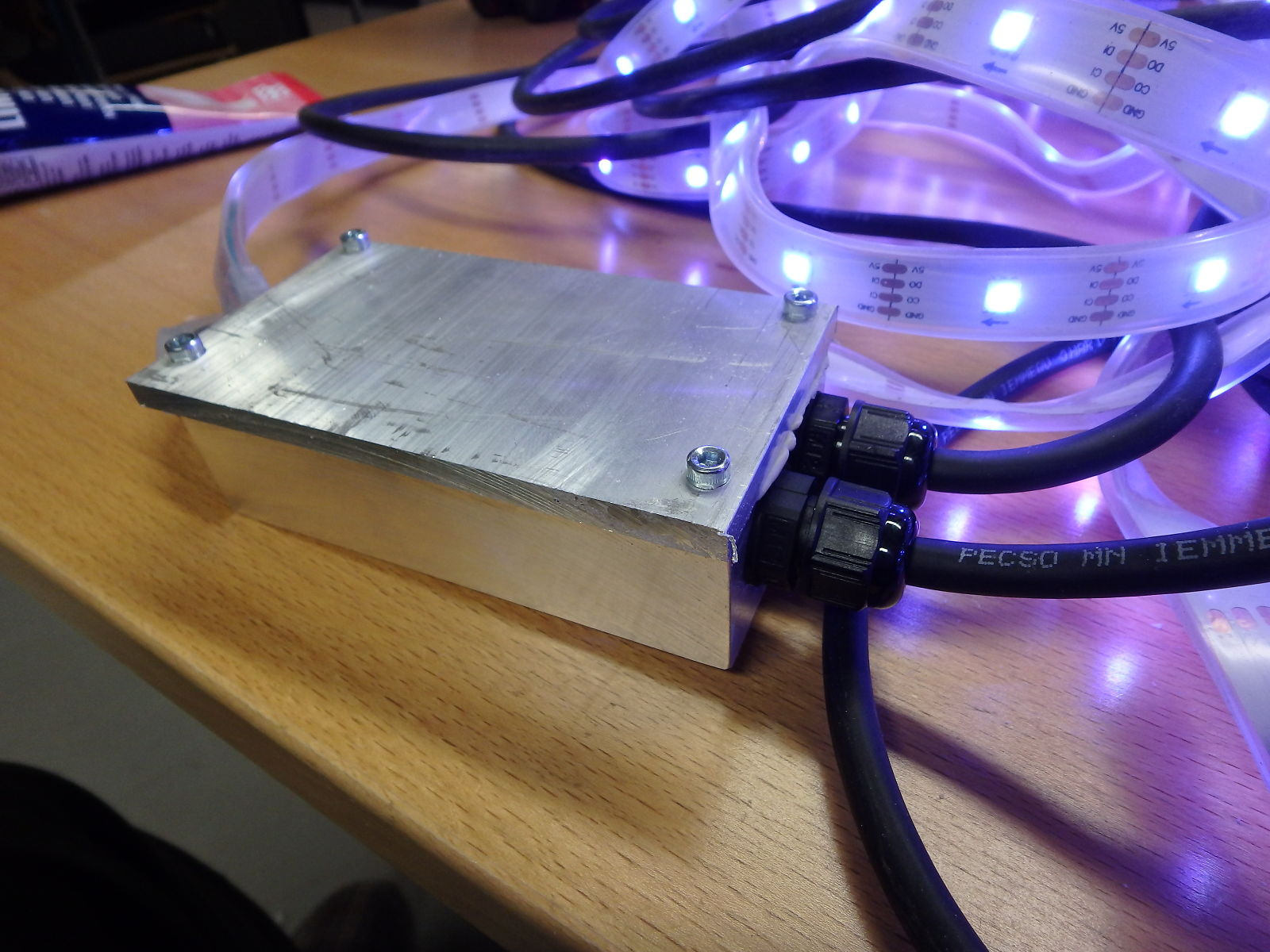
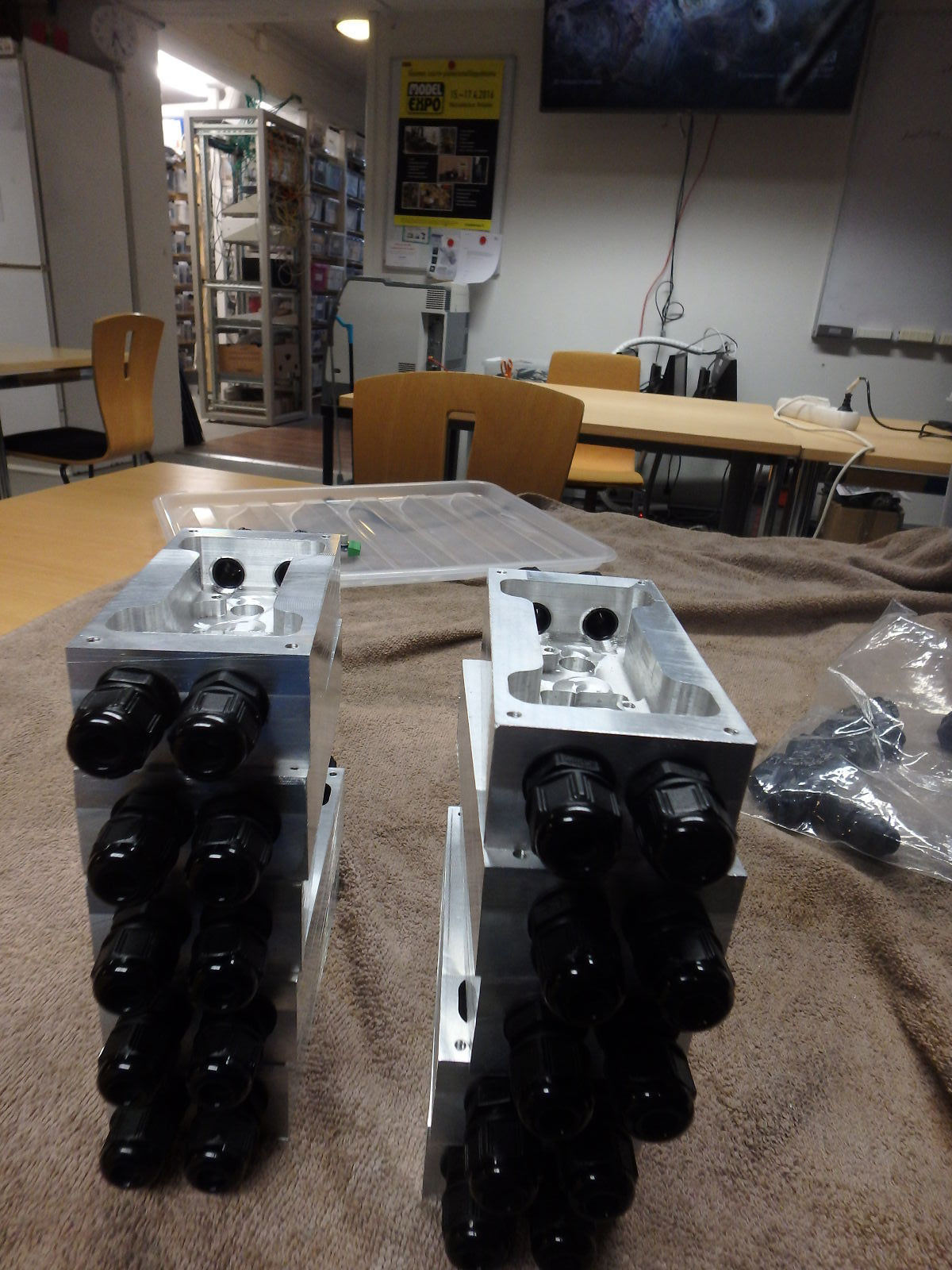
Step thirteen: start attaching all the other stuff you milled these things for. profit ?

Most important notes: for tapping always use spiral fluted tap (it doesn’t strictly have to be a CNC or machine tap), also use exactly correct size hole, if there is no drill of suitable size (there almost never is the sizes are weird), the , drill undersized hole and mill it to correct size (or just get a correct sized drill from Maanterä). If you plan on making more than a few, spend time on optimizing those feedrates or you’ll spend many a night at hacklabs couch waiting for the milling jobs to finish.

1 Like

(in case it was not obvious) I’ve been using Autodesk Fusion 360 for design and CAM, the project is here: http://a360.co/1T23AY5

More randomly ordered stuff

  • 3D pocket is great, use multiple pocket operations with deacreasing tool sizes to get what your need
  • Check the “rest machining” checkbox.
  • Do not use spiral ramps, Fusion doesn’t use G02/G03 for them, instead makes bazillion short moves
    • This is the best way to drastically reduce generated code size
    • For zig-zag ramps you can probably raise the ramp angle to 10-15 degrees or more (depending on tool and whatnot)
  • Use predrill instead of ramps if possible, drilling aluminium can be done silly fast with morse-drills
  • Set the toolholders and adjust tool body lenghts in your project tool library, this way the simulation can take these properly into account when detecting collisions.
  • There is “Use shaft” -checkbox (or something like that, I’ll doublecheck the exact text later) in the 3D pocket operations, use it (this way even if you have slightly too short flute on mill you can avoid shaft collisions when milling deep pockets).
  • Have some idea of what size tools you’ll be using as early as possible, add fillets to your design with the tool radii for inside pocket corners, this way you won’t forget about them when fitting 3D parts together.
  • After CAM simulation you can save the resulting stock as STL, 3D print this for testing part fit in reality (I printed 5 or so test parts and adjusted the design after each one…)

The programs I used (apart from one basically completely handwritten one I used to finish tapping operation aborted earlier due to my straight fluted hand-tap sticking) are available at https://www.dropbox.com/s/0cyy2a7rfjxg4h5/edited_gcodes.zip?dl=1

Edit:

  • “smoothing” doesn’t do what I thought it does (probably applies to you too), “Smoothing” in the operation does try to use G02/G03 (my piece just did not benefit from it) but “use smoothing” in the postprocessor options will add High-Speed-Machining GCodes that Lotta does not support.
  • “use G95” also results in bad code (for Lotta) if you’re doing anything else than just tapping. “Use pitch for tapping” must be used together with “Use G95”: Leave “Use G95” and “Use pitch for tapping” both off in post-processor options

First seven cover plates:

basically just four holes, did the facing using jog mode.

Edit: someone at some point in IRC asked the question “why ? wouldn’t it have been simpler just to buy some hammond cases ?”, the answer has a few parts

  1. Suitable Hammond cases are 10.90EUR a piece, I need 10… 5kg of the alu stock cost me about 30EUR, add 20EUR for the ruined endmill and I’m still 60EUR on top. The stock pieces for the lids are from the random bits and pieces we have laying around at the lab.
  2. This way the inside of the case can be formed around the regulator, acting as heatsink and attaching everything is simple since there is a specific place for each thing.
  3. I wanted to, these are way cooler than boring hammond cases.
  4. Also learning to use the tools (Fusion360, Lotta) better (rigid tapping for example was never done before at the lab)

And the 3 last ones (from a differently shaped leftover piece, I duplicated the previous setup and changed the stock thickness and stock origin point):

@Kremmen found some cheap leadscrew and made these jacks (which are absolutely necessary for support when milling something this thin), used them yesterday too but forgot to take a photo then:

And one of the (last) regulator boxes with the lid attached

I didn’t bother facing anything that was not strictly neccessary to be able to get a straight face against the regulator box face so yeah… a bit of filework needed to make these safer to handle…

Edit: also noticed that some of the M3 screw holes for attaching the lid plate have very poor threads (as in the thread strips crazy easy), so same thing as with the M12, need to buy a sprial-fluted tap for the next time…

1 Like